


PLC Program for logic gates

Implementation of various Logic Gates AND, OR, NOT, NOR, NAND, EX-OR and EX-NOR in PLC using Ladder Diagram programming language.
- Assuming that all the gates comprise two inputs and NOT Gate has only one input, Logic Gates can be well implemented in PLC using Ladder Diagram programming language as shown in “Program” section.
- To implement Examine if closed, Normally Open contact is used and to implement Examine if open, Normally Closed contact is used.
- These contacts is said to work as relay contacts.
- In Normally Open / XIC contact, when logic 1, or in other words, when logic high is provided, the contact closes allowing current to pass through the circuit.
- And in Normally Closed / XIO contact, when logic 1 is not present, or in other words, when logic 0 is present, it allows current to pass through the circuit. But when logic 1 is present in case of XIO, the contact opens inhibiting current to pass through the circuit.
- By simply using these logics, all Logic Gates can be well implemented using Ladder Diagram programming language.
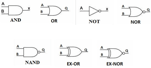
Symbol of Logic Gates
PLC Program
Here is PLC program to implement various logic gates, along with program explanation and run time test cases.
AND
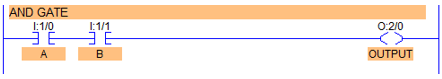
- By connecting Normally Open / XIC contacts in series, AND gate can be implemented.
- When both inputs are set to 1, then and then only output goes high.
OR
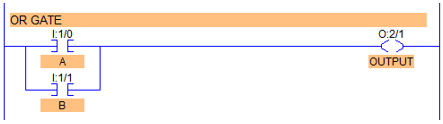
- By connecting Normally Open / XIC contacts in parallel, OR Gate can be implemented.
- When either input is set to high, output goes high.
NOT
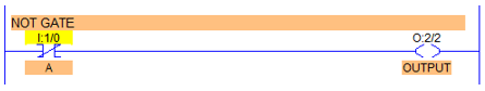
- By using just one Normally Closed / XIO contact, NOT Logic Gate can be implemented.
- Inverted state of input is obtained as an output.
NOR
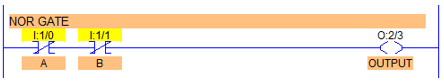
- By connecting Normally Closed / XIO contacts in series, NOR Logic Gate can be implemented.
- If both inputs are Reset to 0, output goes High otherwise remains in Low state.
- Or by inverting output of a OR Gate, that is by using output of OR Gate as an input of NOT Gate, NOR Gate can be implemented.
NAND
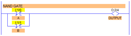
- By connecting Normally Closed contacts in parallel to each other, NAND Gate can be implemented.
- Or by simply inverting output of AND gate, NAND Gate can be implemented.
EX-OR
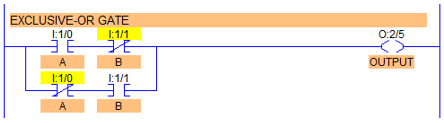
- By connecting XIC and XIO in series with parallel to XIO and XIC in series as shown in diagram above, EX-OR Gate can be implemented.
- When both inputs are identical, output is 0. Output is high when A ≠ B.
- Note here that XIC of first series contacts and XIO of second series contacts must be given same address and similarly for the other two.
EX-NOR
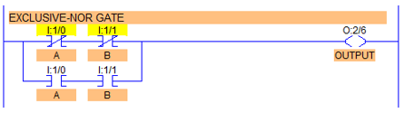
- By connecting two XIO contacts in series with parallel to two XIC contacts in series, EX-NOR gate can be implemented.
- When both inputs are identical A=B=O or A=B=1, output goes high.
- It implies same here as in EX-OR gate that address must be given same.
- – By inverting output of EX-OR gate, implementation of EX-NOR can be accomplished.


0 Comments